Both instrument and scene flux scattered by the earth's atmosphere have large polarization. The protection coating on the silver pointing mirror surface has a polarization phase. To calculate the response to the polarized input scene flux, the polarization reflectivity and phase of the instrument need to be considered. The relation between input flux Stokes vector and two linear polarizations "P" and "S" of TANSO-FTS measurements can be expressed using the Mueller matrix as follows:
 (1)
(1)
 (2)
(2)
where  ,
, ,
, ,
, ,
, , and
, and  are Mueller matrixes of polarization beam splitter, optical efficiency of the FTS-mechanism and aft-optics, phase difference due to the pointing mirror surface coating, pointing mirror reflectivity, and CT rotation, respectively.
  ,
,  ,
,  ,
,  , and
, and  are output and input signals of the Stokes vector and the CT and AT angles, respectively. , the Stokes vector at the top of the atmosphere can be calculated with a vector radiative transfer model. The reference plane for polarization for the input Stokes vector (I, Q, U, and V) is defined by the local normal at the target and the ray from the target to the satellite.
The above mentioned Mueller matrix needs to be used to correct the AT and CT angle dependency of the pointing mirror in the case of slant looking. Thus the correction requires the pointing mirror reflectivity and phase information in  and
and  as the function of AT angle (the incident angle to the mirror) as indicated in Fig. 1 and Fig. 2 (a). These data are acquired with the mirror witness sample, which was coated at the same time as the flight mirrors. This coating has been optimized for the SWIR region with higher than 99% reflectivity and the AT angle dependency of SWIR bands is very small.
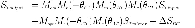
However, the reflectivity is lower and the polarization sensitivity is higher in some TIR wavelength, as shown in Fig. 2 (b). Measured spectral radiance  can be expressed using the scene flux
  , thermal radiation from the pointing mirror, and the back ground radiation in the following Mueller matrix:
 (3)
(3)
where  ,
,  , and
, and  are Mueller matrix of pointing mirror emissivity, Stokes vectors of the radiation from the pointing mirror, and the back ground radiation variation between calibrations, respectively. I component of is retrieved from equation (3) in the TIR Level 1 processing.
(a) Measured phase of the pointing mirror using the witness sample for Mueller matrix of incident angles of 35, 40, 45, 50 and 55 degrees (Band 1).")
(b) Measured phase of the pointing mirror using the witness sample for Mueller matrix of incident angles of 35, 40, 45, 50 and 55 degrees (Bands 2 and 3).")
Fig. 1 Measured phase of the pointing mirror using the witness sample for Mueller matrix of incident angles of 35, 40, 45, 50 and 55 degrees: (a) Band 1 and (b) bands 2 and 3.
(a) Measured spectral reflectivity of the pointing mirror using the witness sample for two linear polarizations (P and S) of the incident angles of 35, 45, and 55 degrees (SWIR).")
(b) Measured spectral reflectivity of the pointing mirror using the witness sample for two linear polarizations (P and S) of the incident angles of 35, 45, and 55 degrees (TIR).")
Fig. 2 Measured spectral reflectivity of the pointing mirror using the witness sample for two linear polarizations (P and S) of the incident angles of 35, 45, and 55 degrees: (a) SWIR and (b) TIR.
