NASA Scatterometer (NSCAT)
provided by NASA

NASA Scatterometer (NSCAT)provided by NASA |
 |

|
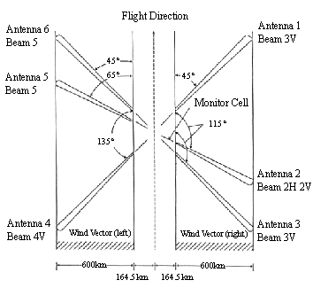
| Antenna Radiation Pattern of NSCAT |
As shown in the figure above, NSCAT makes simultaneous measurements of the backscatter powers with three different directions for each side along the track so that wind speed and direction of the sea surface are inferred. The antenna is with a fan beam of 28 degrees (along the direction of beam radiation). The frequency of backscatter powers in changed by Doppler shift.

| |
| ANT: Antenna ADA: Antenna Deployment Assembly DIU: DC to DC Converter Interface Unit | DSS:Digital Subsystem LRA: Launch Restraint Assembly REU: Radio Frequency Electronic Unit |
| Launch Configuration | |
The Traveling Wave Tube Amplifier (TWTA) in the RF subsystem produces a radar
pulse with 13.995 Ghz (frequency), 5m/sec (width), 62 Hz (repetition frequency).
The pulse is fed to each antenna via switch matrix. After the received signals
are converted to base band frequency level, they are transmitted to the digital
subsystem.
The antenna subsystem consists of six independent fan beam antennas (two pairs
of two antennas and two pairs of a single antenna). Each antenna configuration
is two array antennas with wave guide slots (each for vertical and horizontal
polarization). Two pairs of two antennas use one polarization while the other
antennas do both polarization. The antennas will be deployed after launch.
The backscatter powers, of which frequency is changed by Doppler shift, are
processed by digital Doppler processor in the digital subsystem, and then
transmitted to bus module.
![]() Earth Observation Research Center
Earth Observation Research Center